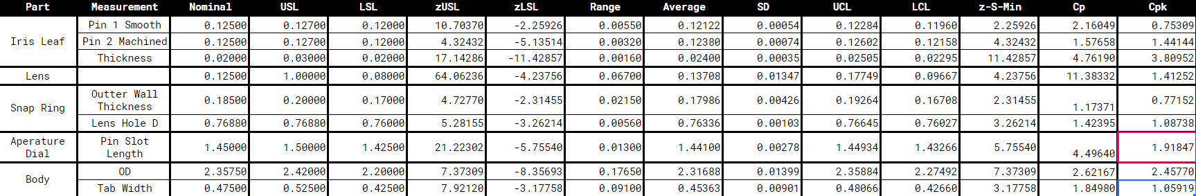
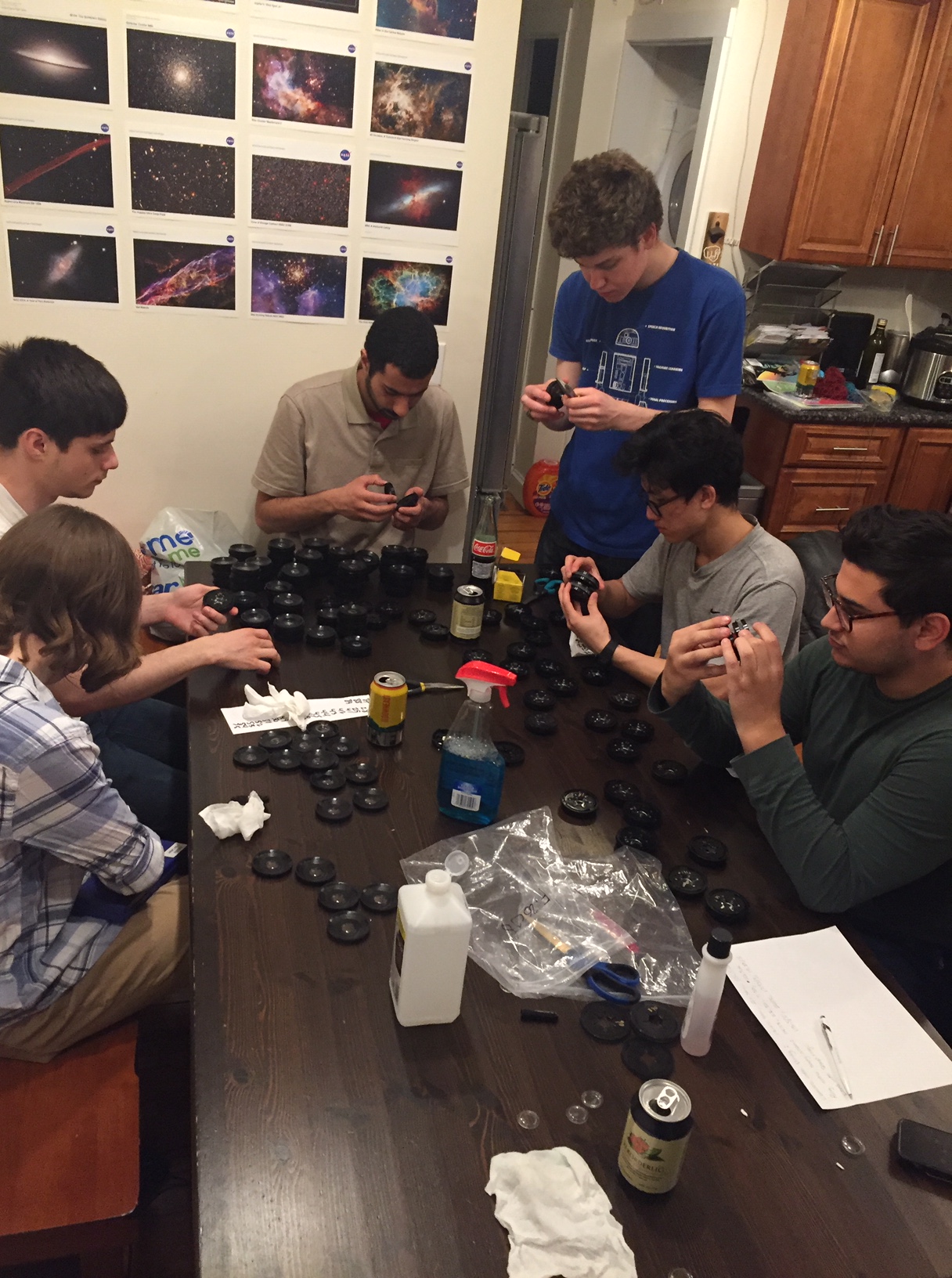
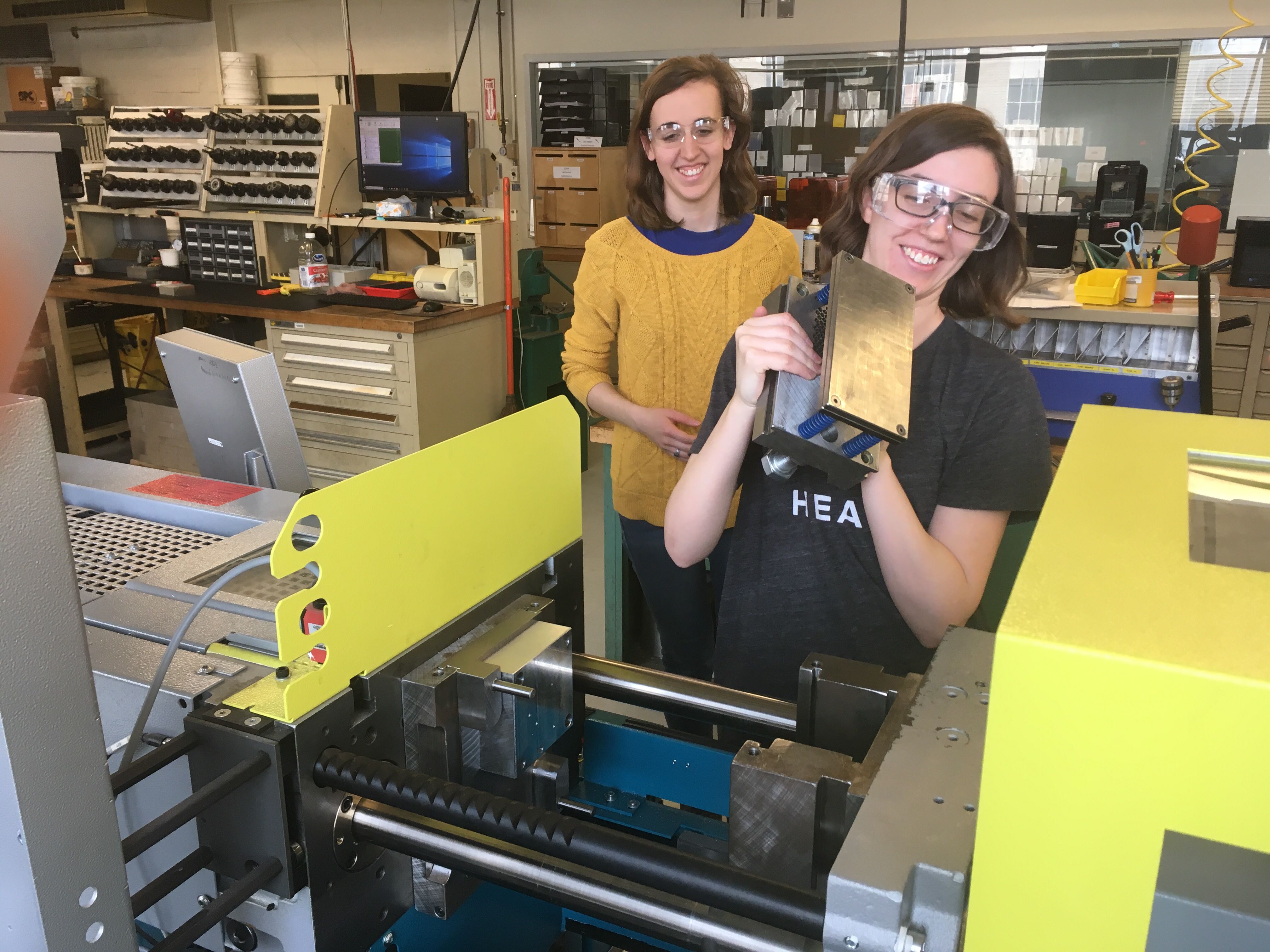
We spent the last 2 weeks finishing mass production of parts and we finally assembled everything on 5/10/19 – 2.5 months after the journey began. We also took measurements of all of our parts and determined the repeatability and control of our process.
Hard at work assembling, jamming to 90s hits.
We fell behind in our schedule between 5/7 and 5/9 because we decided to re-machine the body core mold to include a snap-fit with the mirrors. However, we were still able to complete our production runs before our intended assembly date!
This past week we started our mass production of our yo-yos!
In order to do this we first needed to make some final adjustments several parts:
increased the cooling time of back plate to make it hold it’s shape better
decreased the cooling time of the aperture dial to help it eject without cracking
increased the surface area of our snap fit by making the snap on all four sides of the post instead of just one, and made new mold as necessary to finish it
create a fit for the mirrors on the back body piece
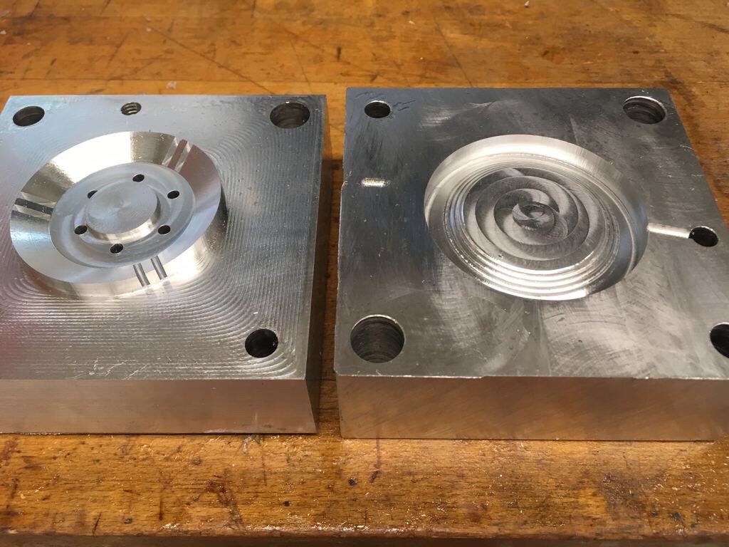
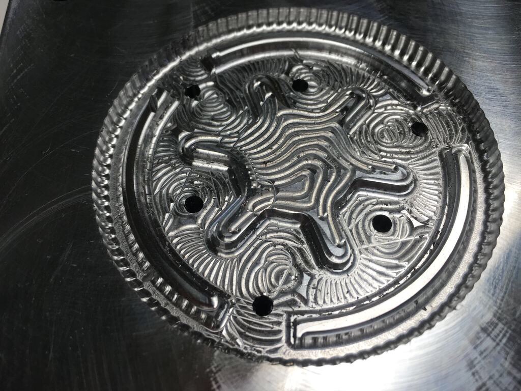
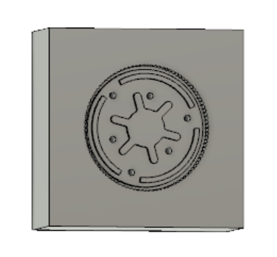
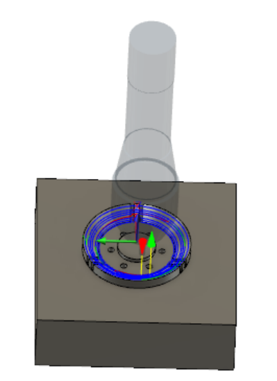
Here is the final core for the snap ring:
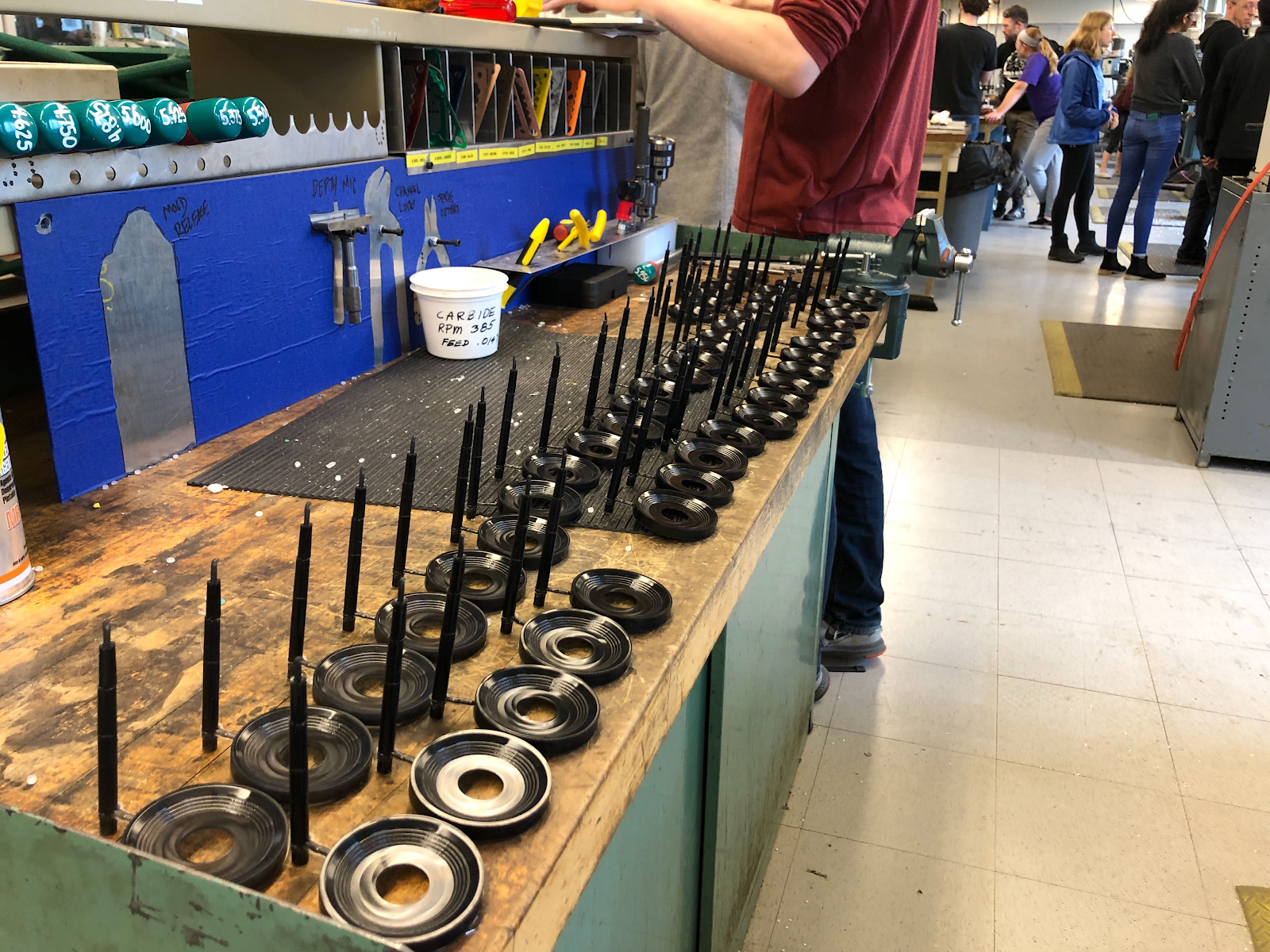
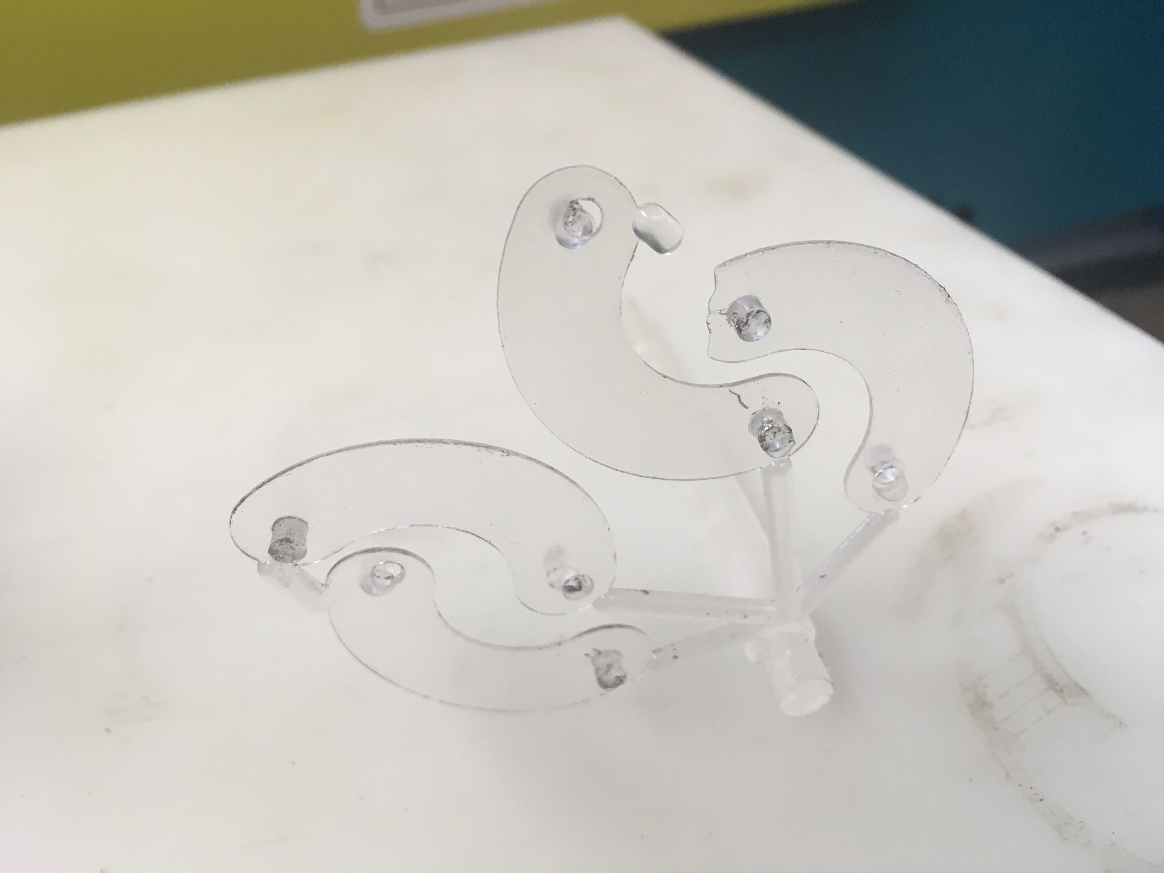
As we began mass producing, we began making our parts in color!
Although most of our parts turned out the nice black color, every once in a while, we would find that the piece turned out slightly more translucent. To avoid problems with that, or anything else, when we began mass producing, we made about 20 extra parts of each kind.
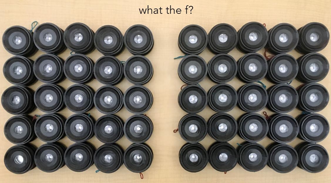
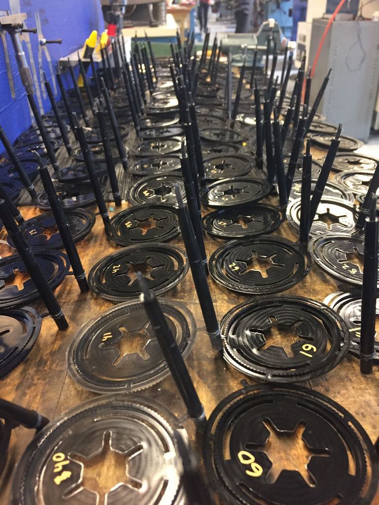
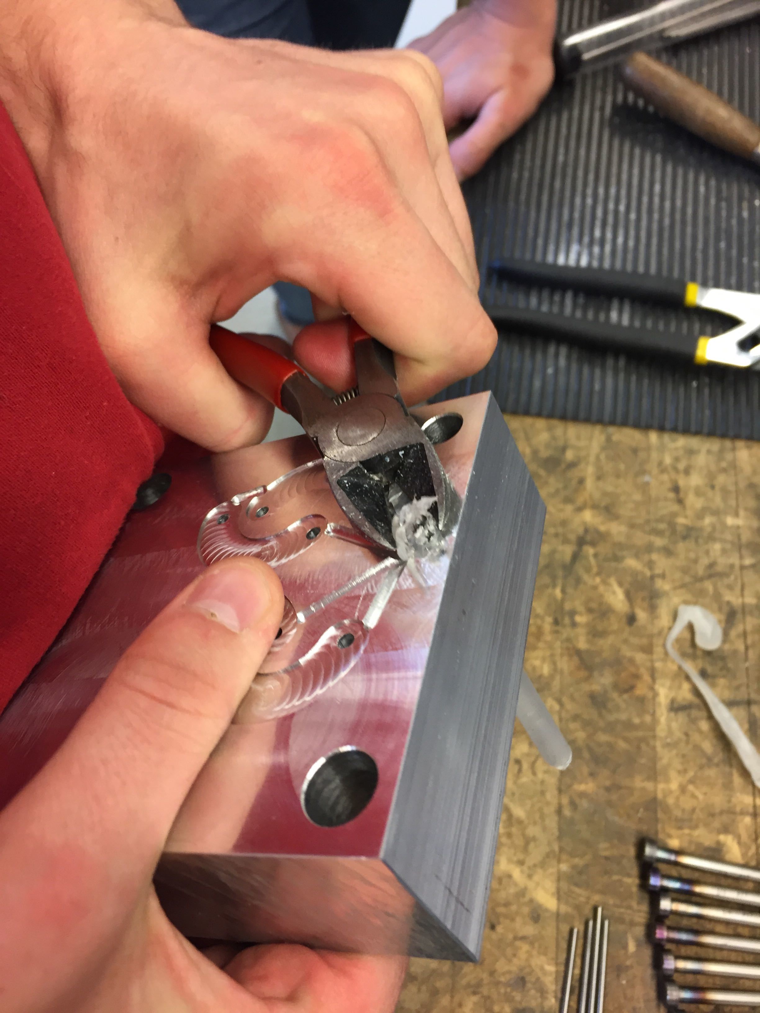
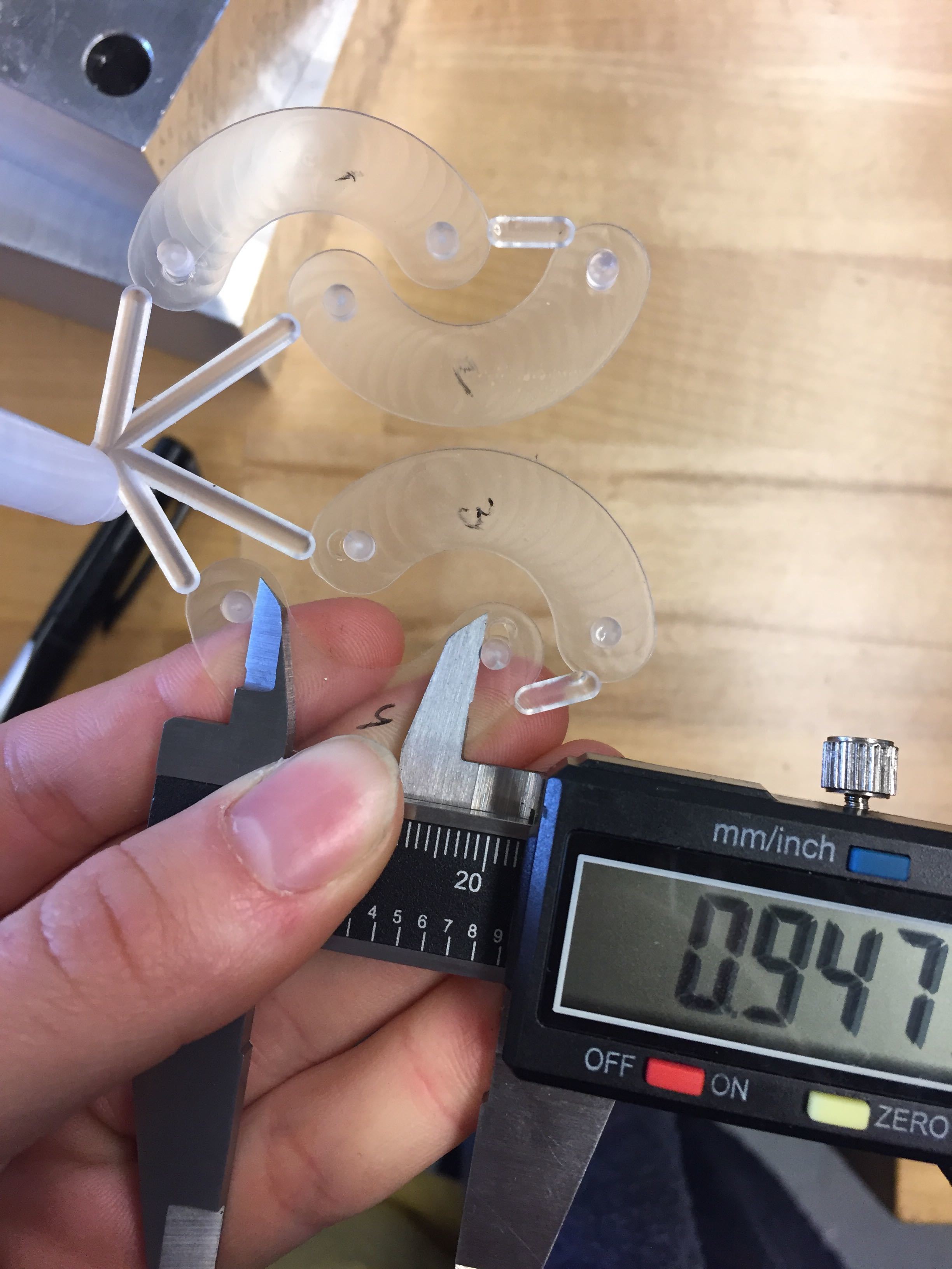
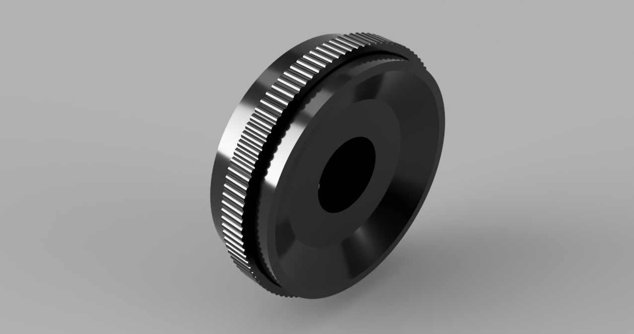
We completely finished producing our aperture dials and snap rings, as shown in the images below. The snap rings have also all been measured already!
Finally, this week, we made a schedule regarding when we would be manufacturing each pieces. In a twist of fortune, we are already ahead of schedule! This is likely due to the fact that we built in some flex time, knowing that some days others might beat us to the machines.
To gain more insight into our scheduling and organization, feel free to look at the schedules and mass production rules below!
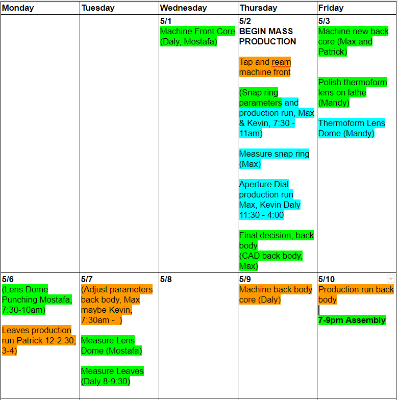
Here is the schedule that we had planned out for ourselves. We have also been keeping track of the actual times we worked on things so we have a good reference for later. So far, we are much ahead of schedule, having already completed the snap ring and aperture ring mass productions.
PLANNED schedule
Monday
Tuesday
Wednesday
Thursday
Friday
4/29
4/30
5/1 Machine Front Core (Daly, Mostafa)
Tap and ream machine front
5/2 (Snap ring parameters, Max, 7:30 – 11am)Kevin???
(Snap ring mass production, Daly, 12:00 – 5)
Final decision, back body
(CAD back body, Max)
5/3 BEGIN MASS PRODUCTION
(Aperture Dial Mandy 12-3pm)
(Leaves Patrick 12-2:30, 3-4)
(Machining back body, Daly 12-5pm)
Polish thermoform lens on lathe (who??)
5/6 (Lens Dome, Mostafa, + someone else for punching?? 7:30-10am)
(Punching, Patrick, 9:30-12:30)
(Aperture Dial, Mandy, 7:30 – 12:30pm, 2 – 5pm)
5/7 (BACKUP Snap ring mass production, Daly, 7:30 – ?)
(Adjust parameters back body, Max maybe Kevin, 7:30am –
5/8 (Leaves Patrick and Mandy 2-3:30, 3:30-5)
(Back body mass produce + someone else, Mandy, 6am – 12pm)
(Patrrick, 9am-12:30)
5/9Backup day
5/10 Lab Catch up day, priority
Assembly
6-8pm Start Assembly (at least half)
BYOB and food delivery
(continued Sunday 5/12 at 12pm)
5/13 Assembly/ Data graphs
5/14 Graphs/ Data graphs Prepare presentation
5/15 Project Presentations!
We also made some rules for ourselves regarding the mass production process to keep things as consistent as possible
Show up as early as possible
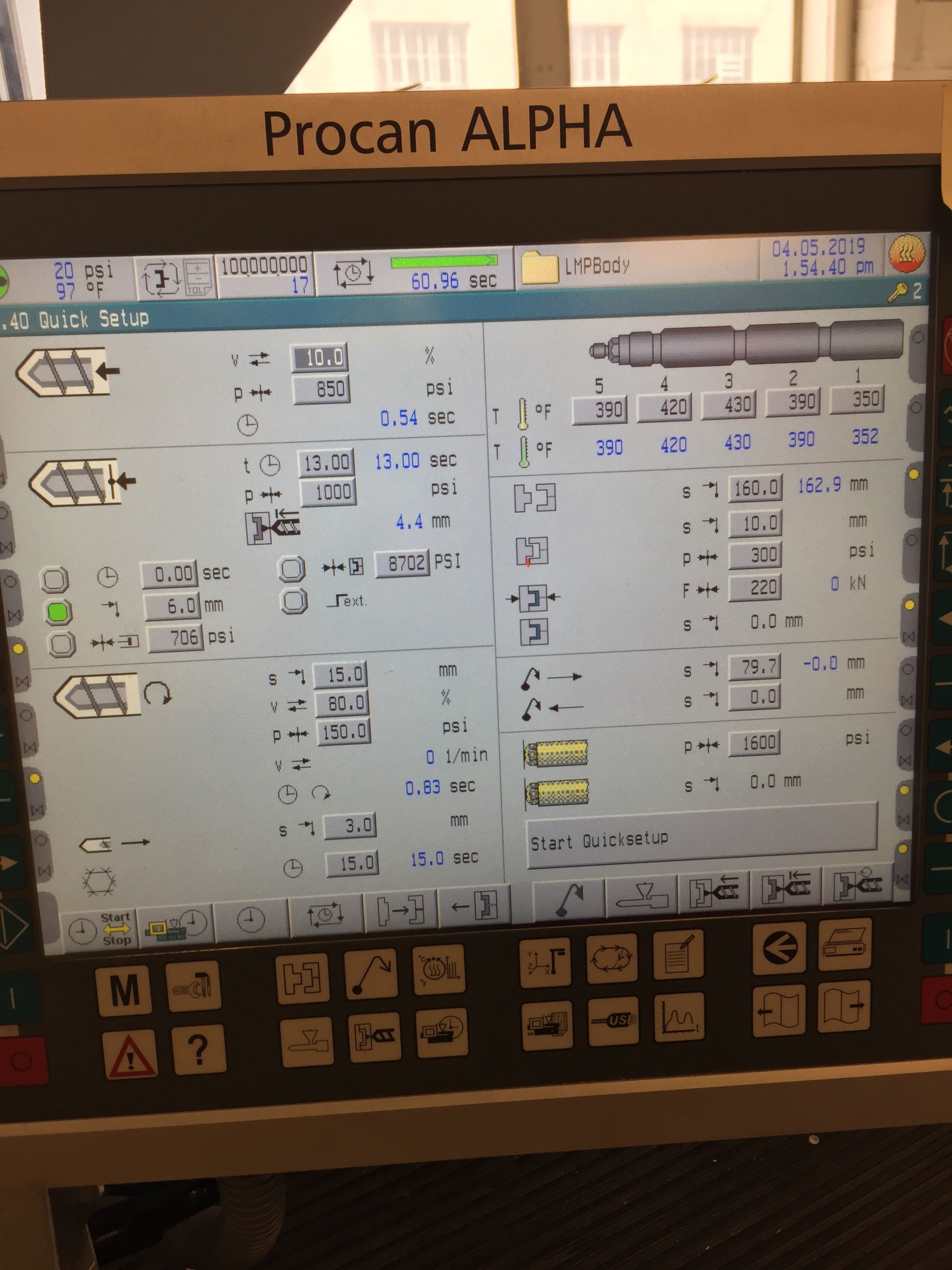
Keep track of all parameters
Keep track of what color and ratio used (be consistent: leaves are silver, all other parts are black)
Label and measure each part as it comes off machine
Keep track of the date the part was made (e.g., parts 1-57 of back body made on date x and parts 58-100 made on date y)
Last week we updated our models to adjust for the 3.3% shrinkage experienced with the injection molding of our iris, by adjust the models nominal size for the shrunken leave then increasing their size by the expected 2.5% shrinkage provided to us for our larger parts. We used these updated models to create V3 molds in CAD.
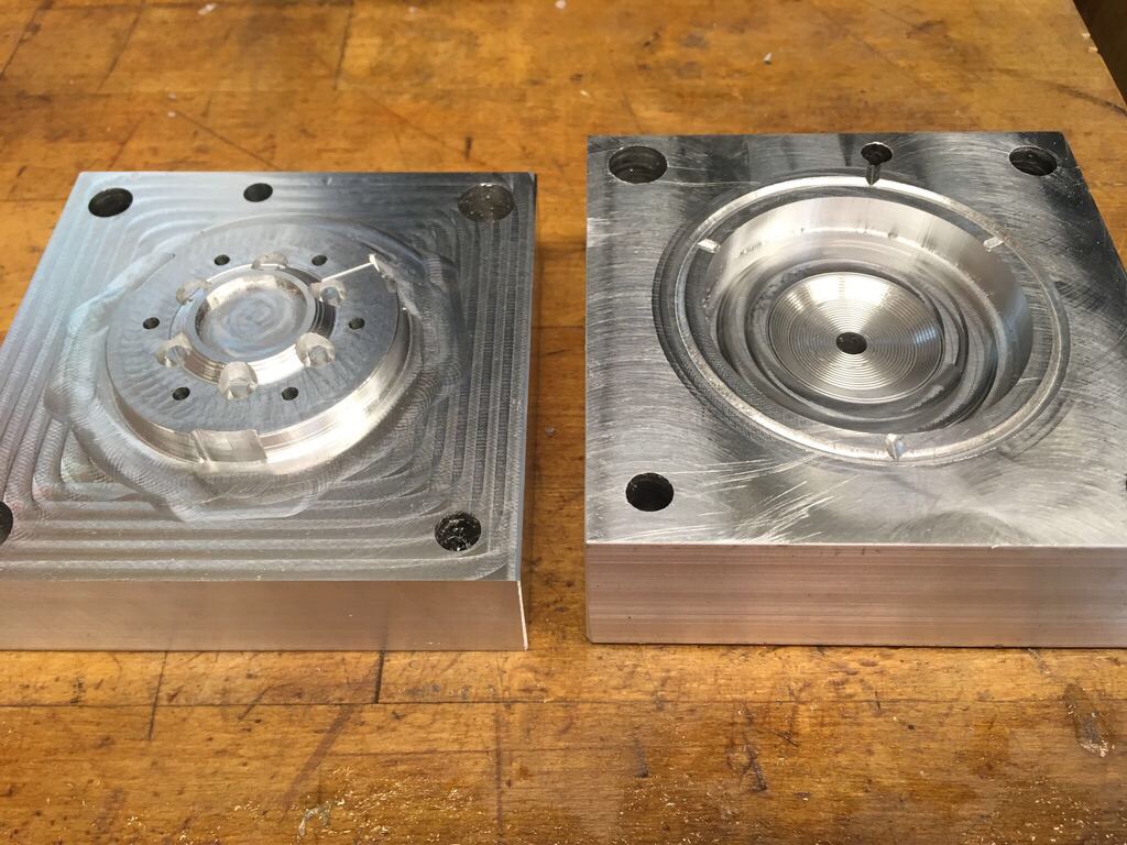
We created CAM for all of our molds and were able to machine our V3 front body mold and V3 back body mold.
Back Body V3 MoldFront Body V3 Mold
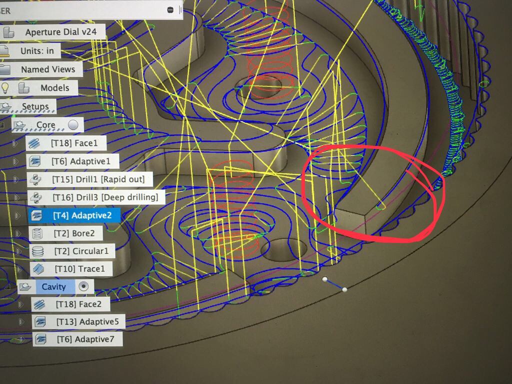
We have attempted to machine our final mold, the V3 aperture dial, but a mislabeled tool has led to a failed mold. We also need to revisit the CAM as there appears to be a missing retraction maneuver that may cause collision.
Next week, we will begin injection mold full yo-yo’s next week.
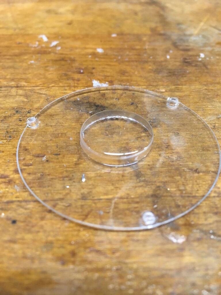
We tested our thermoformed lenses on our 3D printed model. We noticed that the lens rotated with the aperture. To prevent this we updated our lens die and front plate to include 3 pins that will prevent the lens from rotating after assembly. We were able to 3D print, sand, and thermoform with the new die.
Last Friday, we successfully create the core and cavity for our injection molded iris leaves!
The first go around we forgot to use the shear pin, resulting in an unfilled part and and time consuming clean up, but after that we were able to successfully injection mold several leaves!
Despite our close measuring, due to the thinness of the piece, a slight mis-measurement caused the ejector pins to sit too far forward in the mold. It left holes in the iris leaves. In the future, we will have to place additional shims behind core to allow the ejector pins to be level with the piece.
The iris leaves printed, we predicted and designed for a 3% shrinkage. However, after printing many and measuring, we found that ours had a 3.3% shrinkage. Despite the extra shrinkage, when the iris leaves were placed in the 3D printed part, they were still able to function as desired.
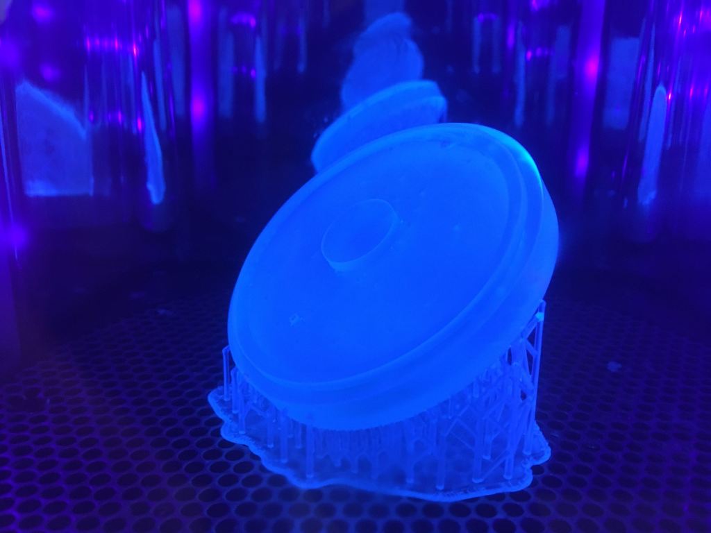
We also printed our die for the thermoformed lens piece, and created our first aesthetic lenses. The lenses were supposed to have a clear, precise look to them, but due to the nature of the 3D printed mold, the final die would need to be polished. In addition, we have decided to make slight changes to the design of the die.
Other than that updated the CAD design to account for the nut and shoulder bolt that would need to be present in the final yo-yo. We also continued to create the CAM needed to machine the molds for the rest of the 3D printed pieces.
As we have been working with the yo-yos, we have realized that the most difficult part of the assembly will come from assembling the iris leaves. Because they overlaps and are generally confusing, we are looking into using an assembly jig to reduce assembly time. The jig would need to align the six leaves so that they can be easily transferred onto the back body piece.
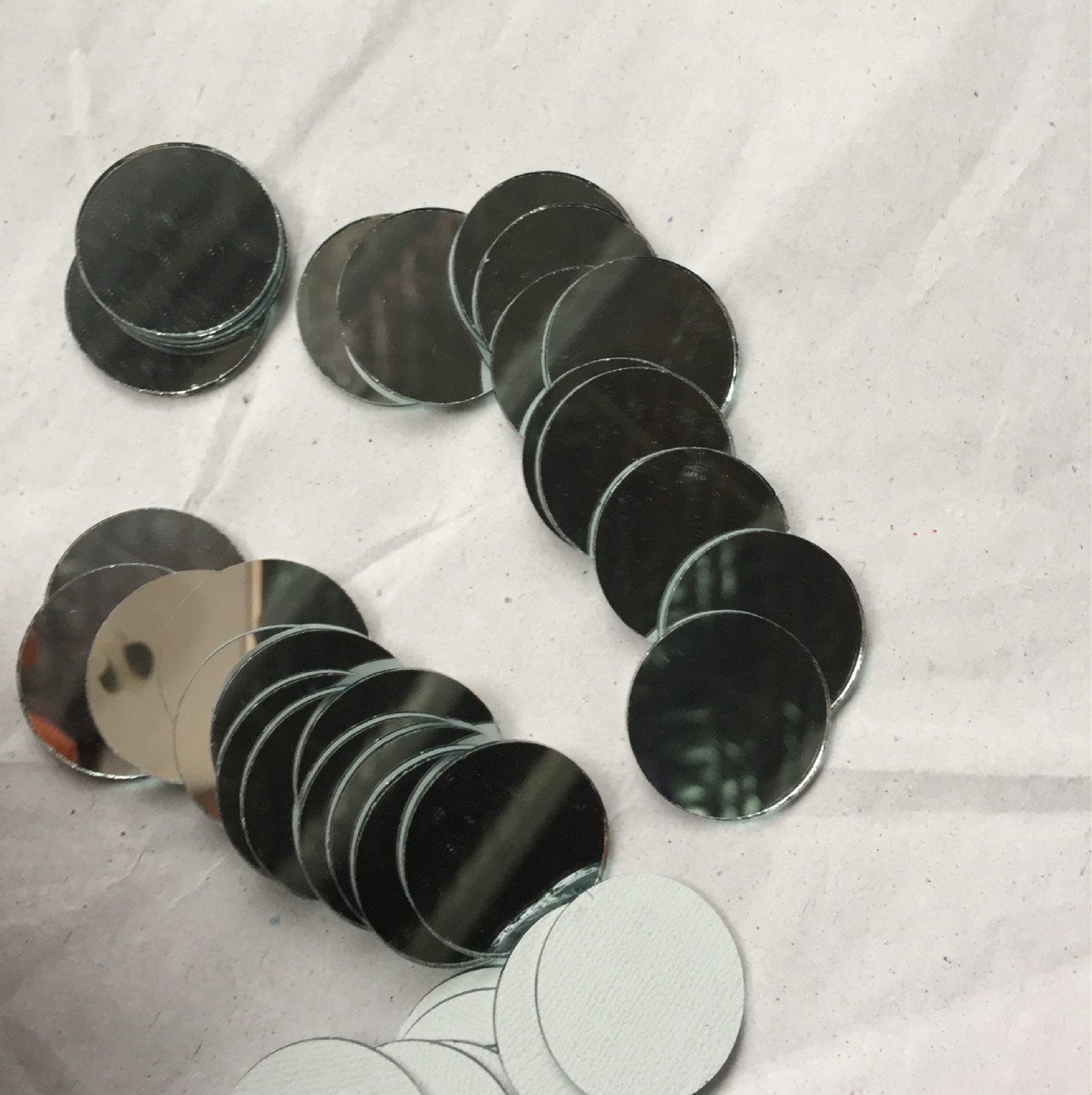
Finally, we found these mirrors online that we thought would make the inside of the camera look really cool. In addition, the mirrors are heavy enough to bring the yo-yo weight up to 62g, which brings the yoyo within the appropriate specifications!
We made a few changes to the design this week to make it better suited for manufacturing:
All extruding features are >1/16” thick so that the negative feature on the mold can be machined with the lab’s smallest end mill, with room for smoothing paths.
The back, internal surface of the yoyo, seen looking through the iris, is larger to create a flat surface. We have talked about ideas for placing a sticker, a mirror, or a nice-looking finish on the back surface.
The front part was simplified by removing the tabs that dictated in what orientation the back and front parts snap-fit together. This was unnecessary and will make assembly easier without the tabs.
Final design of yoyo half
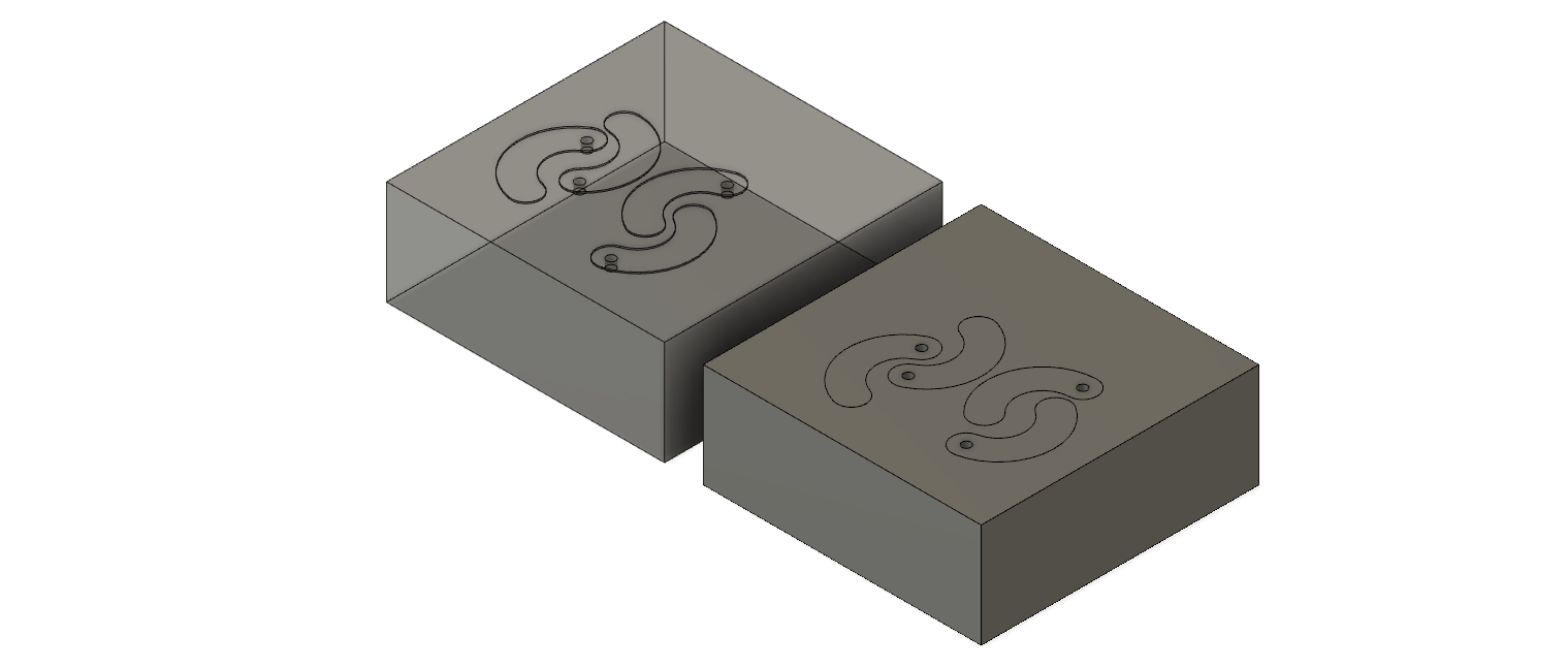
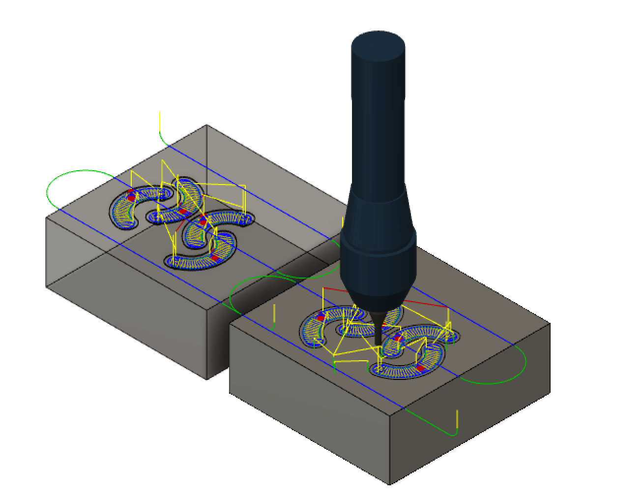
We also created the mold and CAM for the iris leaves. It is important for us to begin with the leaves because they poise an interesting injection molding challenge. Because the parts are so thin, we are uncertain about the effects of shrinkage and the risk of defects such as weld lines and flash. As a baseline, we scaled the leaves by 103% to account for shrinkage. We have estimated the pressure required to injection mold one leaf to be on the order of 10^6 Pa, which is reasonable. With 12 leaves needed per yoyo, it is necessary to make multiple leaves during each injection cycle. We have placed four leaf negatives in the model, orienting them to have balanced flow and minimize the flow distance.
We are getting *focused* and fleshing out our yoyo design this week!
We made a few major decisions as a team:
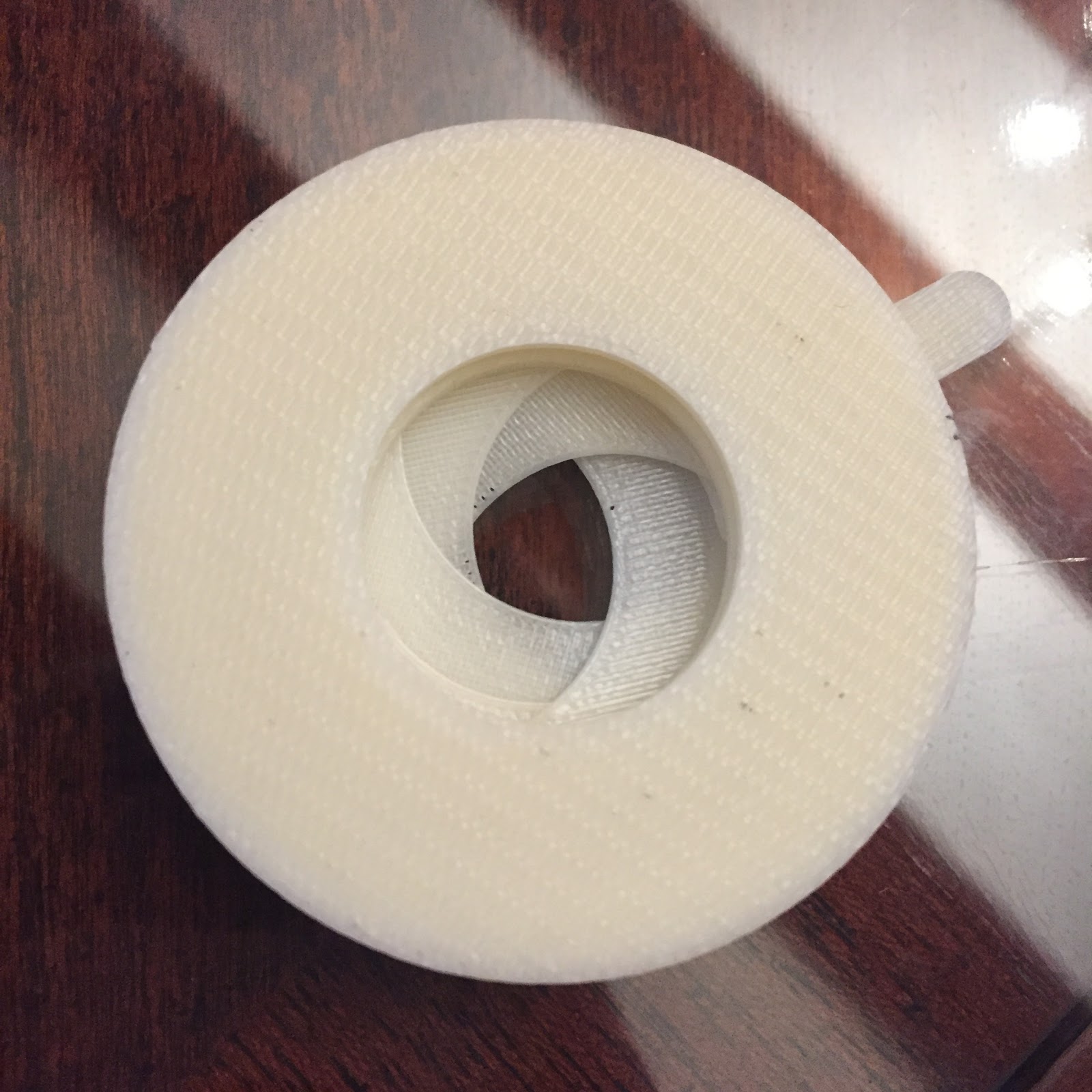
Patrick printed this iris mechanism which is actuated by a tab that comes out of the side. Because the top and bottom of the mechanism remain static, we think this is a good way to incorporate a rotating ring in the middle of the lens. To make the mechanism more applicable to our design, we plan to do the following:
Widen the pins on the iris “leaves” – the parts that open and close the aperture- to make them more robust
Reduce the number of leaves to simplify the mechanism (this one has 6 leaves)
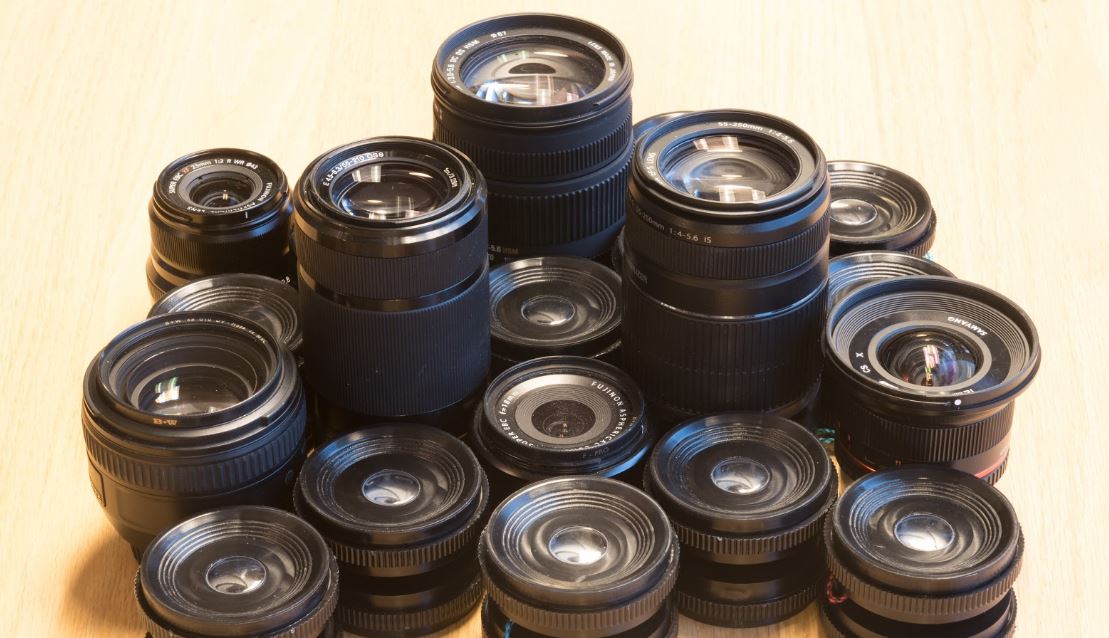
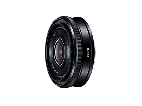
Mandy used a Canon EF 40mm f/2.8 STM lens to extract the major dimensions of our part
Max decided on some important features to include to make the yoyo identifiable as a camera lens:
Aperture ring near the back of the lens
Include smaller diameter mounting ring (which doubles as a good step-down to where the string wraps)
Some type of white text on the side face of the lens
We could spray-paint on “f/2.008” or print out stickers
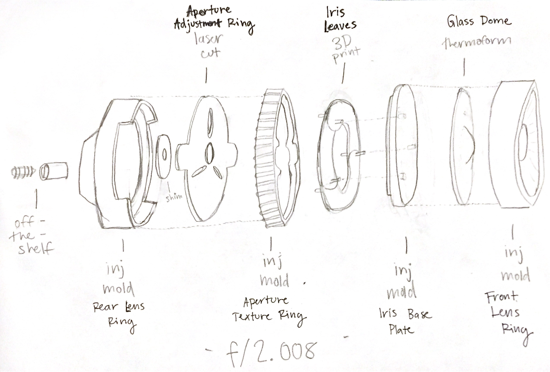
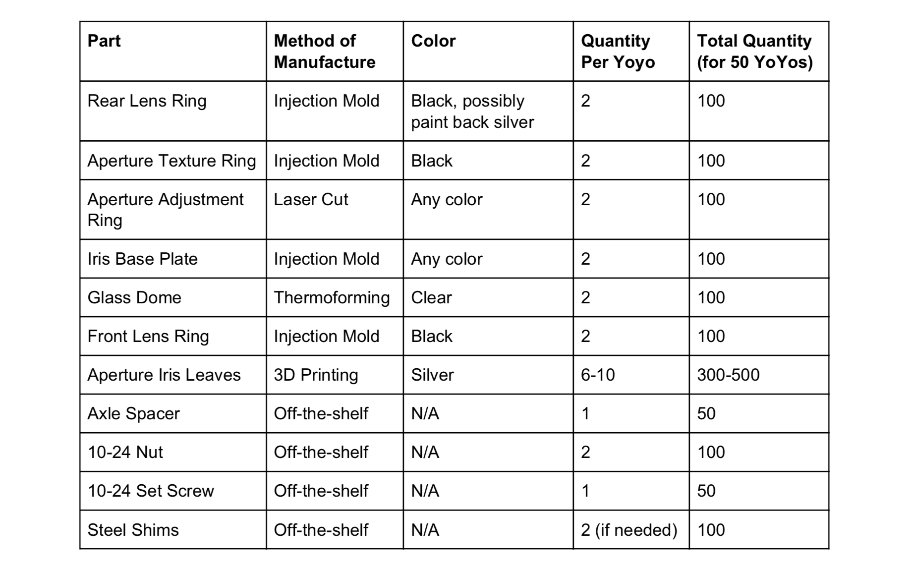
Based on these decisions, this is our anticipated part breakdown:
This comes to a total of 20+ parts per yoyo. We are continuing to think about ways to simplify the iris mechanism, as its design mandates breaking what would normally be a single injection molded piece into 2-3 pieces.
We have a couple of major manufacturing questions going forward:
Iris Leaves. The iris leaves first seem like they would be easy to laser cut or waterjet, but the mechanism requires a pin sticking out of one end. Therefore, we think that 3D printing is the most effective way to product them. However, since 3D printing is slow when producing 300+ parts, we would love more ideas about how to produce the leaves!
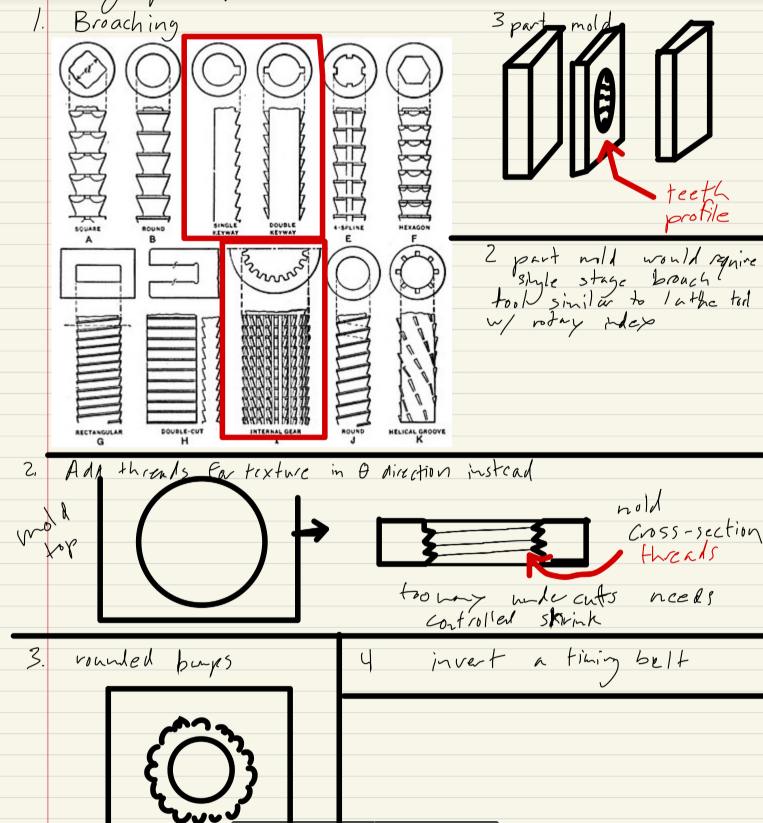
Aperture Ring: Aperture rings have a detailed texture on the side, which is difficult to product in injection molding without creating small cavities for the plastic to get stuck in. Kevin brainstormed a few ways to produce this part:
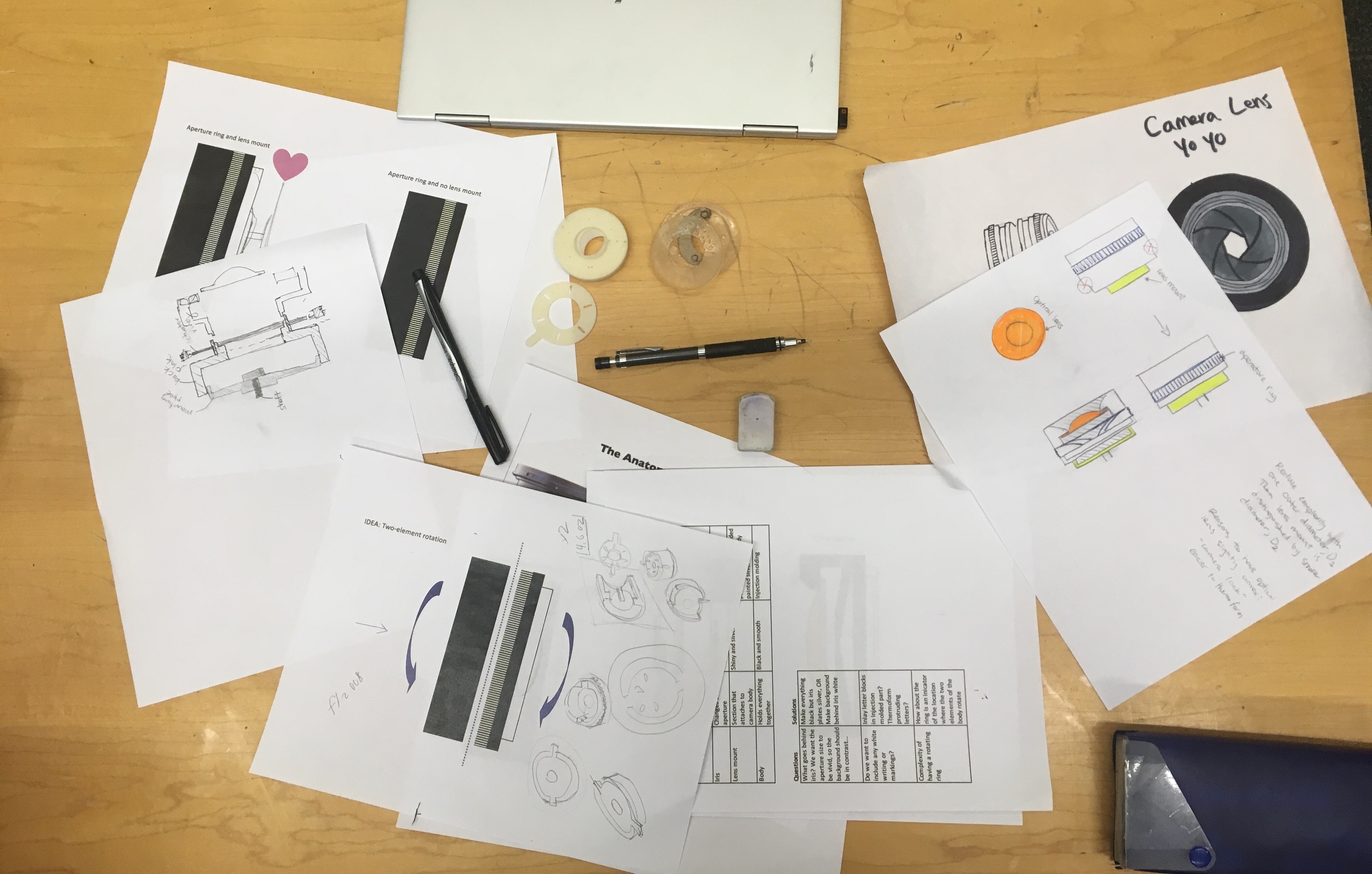
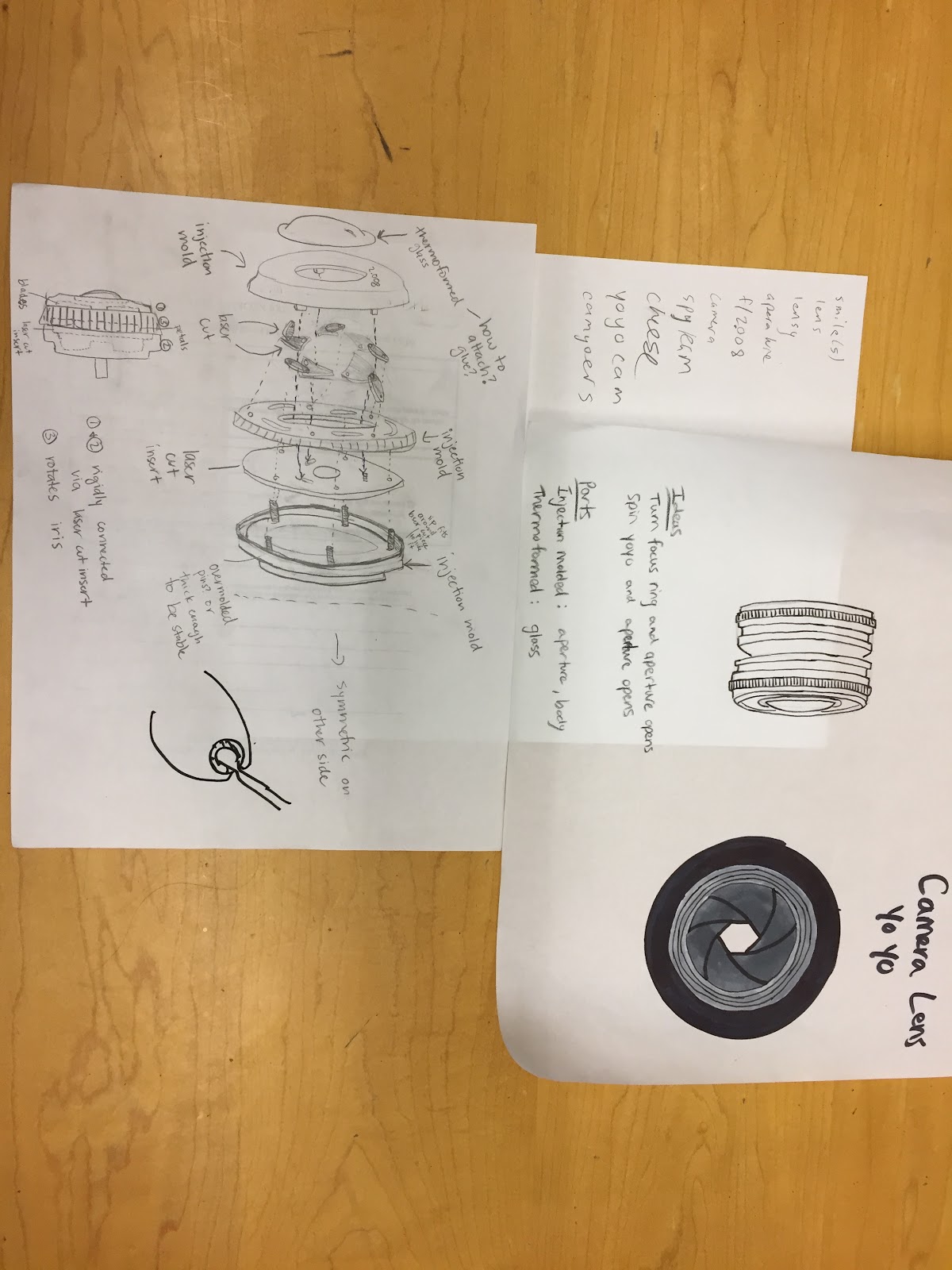
Now that we have our camera design, time to get into the nitty gritty. How will it work? Who are we?
First and foremost is the team name: If you’re familiar with cameras, you probably know that a number like f/2.8 refers to aperture size on cameras. Enough said?
Second, we brought some preliminary ideas of how it might work.
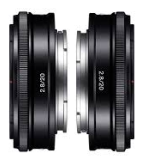
As a refresher, our yoyo concept is a camera lens, like this:
For now we have two options for the design:
Aesthetic camera lens: looks look a camera lens with a nice weight, textured aperture ring, clear dome, and iris.
Mechanically functioning camera lens: same as option 1, but turning the aperture lens actually operates the iris!
The body is made of black and gray injection molded parts
The glass dome is made of clear thermoformed plastic
The iris mechanism may be made of — water-jet metal, 3D printed plastic, or injection molded plastic — spray painted black.
Here are some preliminary sketches of how the iris mechanism works in real cameras!
We decided our next step would be to look into existing CAD for camera irises, as well as begin breaking down how a mold might work for the purely aesthetic portions.
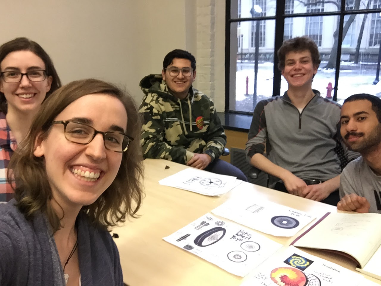
We’ve been working hard brainstorming our yo-yo concept.
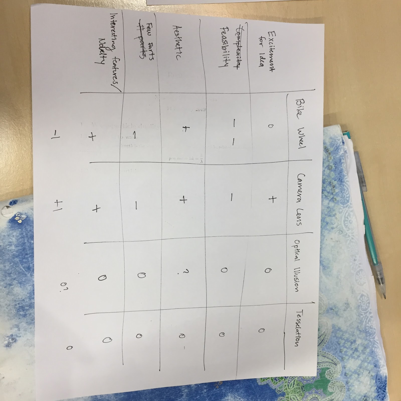
Our team hard at work! Bicycle wheels, optical illusions, peaches, acorns, cameras, googly eyes, and more! A sushi roll too! After choosing our four favorite designs we used a Pugh chart to weigh our options.
We came to this meeting with a variety or ideas. Our only requirement was that three pieces must be injection molded and one must be thermoformed. After taking a look and hearing about them all, we picked our favorite ideas! From there, we discussed why we liked which pieces and came to agreement on the camera lens idea, and agreed to move forward with that.